 Available in all Editions
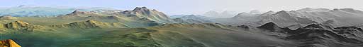
Advanced Perlin Noise is a second generation, highly customizable fractal terrain generator based upon the basic fractal
noise techniques pioneered by Ken Perlin.
Perlin Noise works by layering the output of several sets of noise together. These layers are called octaves. The multiple
octaves are combined together in a variety of ways to create the final
result. Advanced Perlin Noise gives you total control over the types of noise used in each layer, as well as how they are
combined. This allows you to create
some very unique terrain shapes.
| Device Parameters | |||||||||||||||||||||||||||||||
|---|---|---|---|---|---|---|---|---|---|---|---|---|---|---|---|---|---|---|---|---|---|---|---|---|---|---|---|---|---|---|---|
| Feature Size |
Controls the density of features of the terrain.
Feature Size roughly corresponds to the distance between major peaks or valleys. Small values produce quickly changing terrain, suitable for hills or lumps, while middle values are ideal for mountains. Large values allow continents and other shapes that are created on a massive scale. |
||||||||||||||||||||||||||||||
| Style | Change the type of fractal noise that is produced. | ||||||||||||||||||||||||||||||
|
|||||||||||||||||||||||||||||||
| Octaves | Controls the number of layers of noise that are used to create the fractal. The default setting, (automatic), determines the precise number of octaves necessary at the current detail level automatically. Low octave values can produce a very smooth and/or simple terrain, as well as being faster to compute. | ||||||||||||||||||||||||||||||
| Persistence | Controls the degree to which the strength of each layer of noise is reduced as they are layered together. Low persistence values produce very smooth terrains, whereas increasing the persistence produces more detail (and spikiness). Unlike a low octaves value, all layers of noise are still calculated when using a low persistence, so that terrain features are smoothly introduced as the value is increased. | ||||||||||||||||||||||||||||||
| Elevation Center | Adjust the typical middle height of the terrain. Changing this value will produce terrain that is predominantly at lower or higher elevations | ||||||||||||||||||||||||||||||
| Steepness | Adjust the steepness of the grades in the terrain. Low values produce a flatter terrain; High values a steeper one. | ||||||||||||||||||||||||||||||
| Random Seed | Changing the random seed will create new terrain that looks similar to the current one. | ||||||||||||||||||||||||||||||
|
|||||||||||||||||||||||||||||||
|
|||||||||||||||||||||||||||||||
|
|||||||||||||||||||||||||||||||
Available in all Editions A Layout Generator interacts with the Layout View to provide a home for a set of shapes you can use to define terrain shapes, create masks, add roads, and more. When you double click on a Layout Generator, World Machine will automatically launch the Layout View for the appropriate layout. An entire section of the User's Guide is devoted to using Layout Generators and the Layout View; see Chapter 5 of the User's Guide.
Professional Edition OnlyThe Tiled File Input device allows you to load a set of files that together represent a large expanse of terrain. From there, you can work with as large or small a portion of the tiled area as you want. In addition, since the Tiled File Input is simply another device in your world machine workflow, you can have as many input streams as you wish, allowing you to use many possibly overlapping tiled datasets, or to import texturing as well. The User's Guide has a section devoted to working with the Tiled File Input device; see Chapter 10 for more information. The focus here is explaining on what each checkbox or button does.
| Device Parameters | |||||||||||||||||||
|---|---|---|---|---|---|---|---|---|---|---|---|---|---|---|---|---|---|---|---|
| Specify from Files... | Choose the set of files to use as the tiled file input set | ||||||||||||||||||
| Validate Tileset | Click this to validate each of the files in the tileset and make sure they all exist and are the same size | ||||||||||||||||||
| Use Tile Subset | When checked, you can specify a subset of tiles to import with | ||||||||||||||||||
| Interpret as RGB | Import the file data as a Bitmap as checked. | ||||||||||||||||||
| Tiles share edge vertices | If World Machine should assume that the edges of each tile will match. When this option is not set correctly, there will be a one pixel offset in your tileset; Check the export options from World Machine or your other source of tiled data to see what this should be set to. | ||||||||||||||||||
| Flip Y-orientation of tiles | Invert the vertical axis of each file if this is checked. | ||||||||||||||||||
|
|||||||||||||||||||
| Altitude Scaling | Choose how to map elevation data present in the file to World Machine: | ||||||||||||||||||
|
|||||||||||||||||||
|
|||||||||||||||||||
Available in all Editions The Color Generator is the primary way to create colors in your Bitmap networks. It creates a single solid color that exists everywhere in the world; however by using the mask input or combining the output with color generators or other sources of texture, they form the basis of texturing networks.
| Device Parameters | |
|---|---|
| Color | Click on the color to launch the Windows Color Picker for selection. |
Available in all Editions The Mesh Output creates a triangulated mesh from the input heightfield. This is intended for general purpose rendering software or other applications that cannot use a Heightfield; The heightfield should be the preferred output method as it is a much more compact and efficient way of storing terrain data.
| Device Parameters | |
|---|---|
| Mesh Type | Currently, there is only one type of triangulation technique available; this may change in the future. |
| Specify Output File... | Click this to set the filename of the bitmap file using the Windows file dialog. |
| File Name | Edit the name for the exported file. |
| File Format | There is currently only one mesh format available. In the future, there will be several options here. |
| Export using Quads | |
| Output File on every Build | When checked, the output device will export the bitmap on every build. |
| Participate in Tiled Builds | When checked, this output will export tiles during a tiled build. |
| Write Output to Disk | When pressed, will write the build results to the file you've specified. |
Available in all Editions The Bitmap Output allows you to export a Bitmap datatype to a file. You may export to either 8 or 16bit per channel color formats.
| Device Parameters | |
|---|---|
| Specify Output File... | Click this to set the filename of the bitmap file using the Windows file dialog. |
| File Name | Edit the name for the exported file. |
| File Format | Choose a file format for export; there are both 8 and 16bit bit per channel formats available. |
| Output File on every Build | When checked, the output device will export the bitmap on every build. |
| Participate in Tiled Builds | When checked, this output will export tiles during a tiled build. |
| Blend Across Tiles | This option only matters during a tiled build; it controls whether the between-tile blending should apply to the bitmap output or not. There is generally no reason to disable this, unless you are using color keying that depends on specific colors retaining their value. |
| Write output to disk! | When pressed, will write the build results to the file you've specified. |
Available in all Editions The Convexity Selector discovers areas of the input terrain that are either highly exposed (convex) or recessed (concave). Convex areas are white (one), while concave areas are black (zero). Neutral areas that are neither will be neutral grey. This device can be very useful for texturing to either to help shadow recessed cracks in the terrain, or to bring out ridges and other areas that are highly exposed.
| Device Parameters | |
|---|---|
| Strength | The Strength parameter determines what level of convexity maps to the largest allowable mask value. |
Available in all Editions The Lightmap Generator produces a mask of light and shadow (called a Lightmap) that can be used in many applications to illuminate the terrain easily. The Lightmap Generator supports Raytraced lighting, and the output can be either exported to a file (by connecting a File Output node), or it can be used within World Machine to combine with a texturemap to produce a fully lit texture.
| Device Parameters | |||||||
|---|---|---|---|---|---|---|---|
| Illumination Model | |||||||
|
|||||||
| Included Lighting | |||||||
|
|||||||
| Produce RGB Lightmap | Check this option to produce a color bitmap rather than a heightmap mask for output. This will also enable the ability to set the color of the sun and sky. | ||||||
| Soft Clipping | Soft clipping uses an exposure function to combine the diffuse and sky light components together. It only has a significant effect when the combined intensity is greater than 90% of maximum. | ||||||
| Use Global Light Direction | When checked, the Lighting Generator will use the same lighting angle as the one specified in the leftside view and used in all the other previews. | ||||||
| Sun Heading | The heading of the sun, otherwise known as the compass direction the sun is shining from. | ||||||
| Sun Altitude | The elevation of the sun with respect to the horizontal. | ||||||
| Sky Lighting Level | The amount of light illuminating the terrain from above; this represents the contribution of clouds and light scattering. | ||||||
| Diffuse Level | The amount of light produced by the sun. | ||||||
| Sun Color | Select this to set the lighting color of the sunlight (diffuse light) in the scene. | ||||||
| Sky Color | Select this to set the lighting color of the skylight (ambient / light from above). | ||||||
Available in all Editions The normalmap generator encodes the terrain normal into an RGB texture; each direction component of the normal is mapped to a color. (R=X, G=Y, B=Z) is the default encoding. Among other uses, this information can be then used over a low-resolution mesh, giving much of the feel of a high resolution terrain with a fraction of the geometry data.
| Device Parameters | |
|---|---|
| Encoding Type | There is only one type currently for normal encoding: each axis is mapped to one of the three primary channels as noted. |
| Flip X | Flip the encoding so that a positive X axis component is mapped to -127 instead of 127. |
| Flip Y | Flip the encoding so that a positive Y axis component is mapped to -127 instead of 127. |
Available in all Editions Map a color gradient to an input heightfield such that the values in the heightfield determine the color.
| Device Parameters | |
|---|---|
| Color 1 | Choose the bottom color of gradient |
| Color 2 | Choose the top color of the gradient |
Available in all Editions The Channel Splitter converts a Bitmap data packet into 3 individual component heightfields. You can use then use the individual channels in any manner you wish. You can split the bitmap into either Red/Green/Blue channels, or Hue/Saturation/Luminosity channels.
| Device Parameters | |||||
|---|---|---|---|---|---|
| Channel Type | |||||
|
|||||
Available in all Editions The Channel Combiner recombines three individual heightfields into a Bitmap packet. The opposite of the Channel Splitter, this device can treat the three heightfields as either Red/Green/Blue or Hue/Saturation/Luminosity values.
| Device Parameters | |||||
|---|---|---|---|---|---|
| Channel Type | |||||
|
|||||
Available in all Editions
The Coastal Erosion device provides a quick approximation to the effect of large bodies of water on land; specifically,
you can
define a waterlevel and all adjacent heights will be adjusted so as to produce a beach and bluff region adjacent to the
water.
Note that the Coastal Erosion device does not perform any simulation to achieve its result, which has the benefit of making
it very fast.
However, the output is not as complicated as other simulation-based World Machine devices.
| Device Parameters | |
|---|---|
| Simulation Type | There is currently only the basic water simulation available; this produces a fast but not geologically accurate result. |
| Use Global Water Level | When checked, the water level will be taken from the water level specified on the leftside toolbar rather than the Water Level parameter. This is useful because the coastal waterlevel used will match the waterlevel displayed in WM2. |
| Water Level | The elevation of the global waterlevel that will produce the beaches. |
| Beach Size | How wide a zone around the water should be converted to beach. |
| Transition Zone | Control how the beach leads into the terrain. Smooth will produce a smoother transition area, while Cliffs will produce bluff-like features. |
| Transition Power | Low transition power flattens the beach less, while high values will produce a very flat beach with a sharper transition to the regular terrain. |
| Smooth Underwater Features | When checked, features below the waterline will be smoothed. |
| Smoothing Amount | The amount of smoothing to apply to underwater features. |
Available in all Editions
The Snow device simulates the accumulation of snow on the terrain. By varying the parameters, you can achieve results ranging
from a slight dusting
of snow to glacial accumulations. Note that unlike texture-based snow, the Snow device performs simulations and actually
modifies the terrain heights,
producing a very realistic snow effect.
| Device Parameters | |
|---|---|
| Intensity | Intensity controls the amount of snow deposited during a given period of time during the simulation. Larger values will accumulate more quickly; smaller values will settle faster into gullies in the terrain. |
| Evaporative Balance | The evaporative balance controls how fast snow will evaporate from the terrain relative to the snow intensity. A value of 1.0 means that snow evaporates at the same rate it is deposited. |
| Snow Amount | The duration of the snow simulation. Greater values will deposit more snow and allow drifts to travel farther, however it will be slower to process. |
| Snow Line | Specifies the elevation below which evaporation is greatly increased. |
| Linear Depthmask | When this is checked, the depthmask output of the Snow device will contain the exact depth of snow at all locations. When unchecked (the default), the output is scaled logrithmically by the Depthmask Cutoff to produce the mask, producing a visuaully useful result. |
| Depthmask Cutoff | The scaling factor used to construct the snow mask. Lower values will show only the deepest areas of snow, while high values will show even those regions with low accumulation. |
| Taper Snowfall | When checked, the snowfall intensity is reduced towards the end of the snow simulation; when unchecked, new snow is produced even in the very last steps of the simulation. Toggling this option on can be useful when attempting to produce features such as glaciers that represent accumulation over a long time period. |
Available in all Editions
Perlin Noise is a noise function developed by Ken Perlin.
By itself perlin noise produces output that looks something like lumps
scattered about the world in random intensities. By layering multiple perlin
noises at different frequencies and amplitudes, fractal noise functions
that look to varying degrees like mountains can be created.
Perlin Noise serves as an extremely useful building block.
It can be used as the basis for a terrain, to randomize the application of
effect filters, and much more.
| Device Parameters | |||||||||||||||||||||||||||||||
|---|---|---|---|---|---|---|---|---|---|---|---|---|---|---|---|---|---|---|---|---|---|---|---|---|---|---|---|---|---|---|---|
| Feature Size |
Controls the density of features of the terrain.
It roughly corresponds to the distance between major peaks or valleys. Low values produce quickly changing terrain, suitable for hills or lumps, while middle values are ideal for mountains. Large values allow continents and other shapes that are created on a massive scale. |
||||||||||||||||||||||||||||||
|
|||||||||||||||||||||||||||||||
| Octaves | Controls the number of layers of noise that are used to create the fractal. The default setting, (automatic), determines the precise number of octaves necessary at the current detail level automatically. Low octave values can produce a very smooth and/or simple terrain, as well as being faster to compute. | ||||||||||||||||||||||||||||||
| Persistence | Controls the degree to which the strength of each layer of noise is reduced as they are layered together. Low persistence values produce very smooth terrains, whereas increasing the persistence produces more detail (and spikiness). Unlike a low octaves value, all layers of noise are still calculated when using a low persistence, so that terrain features are smoothly introduced as the value is increased. | ||||||||||||||||||||||||||||||
| Offset | Used by the multifractal style variants above, offset determines at what elevation the fractal behavior begins to change its character. Since each variant uses the value here in a slightly different manner, the best guide to its use is experimentation. | ||||||||||||||||||||||||||||||
| Gain | Another multifractal parameter, Gain typically controls the relative strength of the detailed versus smooth regions of the fractal. Low values are very smooth, while high values bring on the detailed nature more quickly. | ||||||||||||||||||||||||||||||
| Random Seed | The value used to begin, or �seed�, the random number generator for this device. Different seed values will produce similar features but in completely different locations. | ||||||||||||||||||||||||||||||
| Use Stabilized Noise | Stabilized noise refers to whether or not the noise should be rescaled to fill the entire height range of the terrain quad. The default is checked; this means that the terrain is NOT rescaled, and thus will remain the same if the terrain is panned around the world; thus the term �stabilized�. There is usually little reason to uncheck this, and doing so will interfere with panning or scaling of the terrain. | ||||||||||||||||||||||||||||||
| Enable Distortion Input | When checked, an optional input is revealed on the Perlin Noise device that accepts a heightfield. The distortion input allows you to shift the coordinates that are fed into the Perlin Noise device in a certain direction; this allows some very interesting effects to be created. | ||||||||||||||||||||||||||||||
|
|||||||||||||||||||||||||||||||
Available in all Editions Voronoi noise implements a cellular texture basis function as described by Steven Worley. Voronoi noise has sharp discontinuities (ridges), and can form the basis for some very interesting terrain effects.
| Device Parameters | |||||||||||||
|---|---|---|---|---|---|---|---|---|---|---|---|---|---|
| Feature Size |
Controls the density of features of the terrain. It roughly corresponds to the distance between major peaks or valleys. Low values produce quickly changing terrain, suitable for hills or lumps, while middle values are ideal for mountains. Large values allow continents and other shapes that are created on a massive scale. |
||||||||||||
| Style | The Voronoi styles are difficult to describe. Each produces a different character of output ridges; experimentation is really the only guide to what style may look good in what circumstances. | ||||||||||||
|
|||||||||||||
| Distance Function | How the device measures distance to the nearest point. | ||||||||||||
|
|||||||||||||
| Random Seed | The value used to begin, or �seed�, the random number generator for this device. Different seed values will produce similar features but in completely different locations. | ||||||||||||
| Enable Distortion Input | When checked, an optional input is revealed on the Voronoi device that accepts a heightfield. The distortion input allows you to shift the coordinates that are fed into the Perlin Noise device in a certain direction; this allows some very interesting effects to be created. | ||||||||||||
|
|||||||||||||
Available in all Editions The Constant generator simply creates a level, flat terrain of a constant height.
| Device Parameters | |
|---|---|
| Height | The height at which to create a flat plane. |
Available in all Editions The Gradient generator produces a constantly sloping plane that is optionally tiled or clipped in world space.
| Device Parameters | |||||||
|---|---|---|---|---|---|---|---|
| Direction | The direction of increasing value of the plane. 0 = east, 90 = north, 180 = west, 270 = south. | ||||||
| Width | The amount of space used to transition from low to high. Specified in world coordinates, the default is 1.0. | ||||||
| Tiling | The Tiling Method describes how to deal with areas that lie outside of the "primary" gradient location. | ||||||
|
|||||||
Available in all Editions The Radial Gradient generator creates shapes that are all centered around one point in space.
| Device Parameters | |||||||||||
|---|---|---|---|---|---|---|---|---|---|---|---|
| Radius | How large an area the shape should cover. The default value is 1.0, which happens to completely fill the default terrain extents. | ||||||||||
| Type | Defines the profile of the radial gradient. | ||||||||||
|
|||||||||||
Available in all Editions The File Input imports a bitmap or terrain file from disk and inserts it into the world at a location and scale specified. The File Input device can read TER, BT, HFZ, PNG, TIFF, BMP, TGA, R32, R16, and RAW formats.
| Device Parameters | |||||||||||||||||||||
|---|---|---|---|---|---|---|---|---|---|---|---|---|---|---|---|---|---|---|---|---|---|
| Load | This button brings up a dialog to specify the file to load from disk. | ||||||||||||||||||||
| Refresh from File | This command instructs the File Input device to reload the file from disk. This is useful if you have the file open in another editor and have made a change that you want to transfer into World Machine. | ||||||||||||||||||||
| Use absolute path | If this is checked, the filename chosen by clicking the Load button will contain the full path to the input file. Otherwise, it will only contain a relative path to the file if possible. | ||||||||||||||||||||
| Auto-refresh from file every build | If this is checked, every time you build the world (press the Green build button), the File Input device will re-read and import the bitmap data from the file. This can be used to, for example, read back in the exact same file that later in the network gets exported, allowing you to produce a terrain that gets slowly eroded through multiple output steps, for example! | ||||||||||||||||||||
| Interpret as RGB | Import the file data as a Bitmap as checked. | ||||||||||||||||||||
| Flip Y-axis | Invert the vertical axis if this is checked. | ||||||||||||||||||||
| Outside Behavior | Controls what the device outputs outside of the world space area specified by the worldspace placement. | ||||||||||||||||||||
|
|||||||||||||||||||||
| Edge Blending | The File Input device exports a blending area around the input terrain as an additional mask. This slider controls how large a percentage of the file input area is consumed by the blending zone. | ||||||||||||||||||||
|
|||||||||||||||||||||
| Altitude Scaling | Choose how to map elevation data present in the file to World Machine: | ||||||||||||||||||||
|
|||||||||||||||||||||
Available in all Editions
The File Output device saves the fully built heightfield to disk.
Only the heightfield information is saved -- any color-height mapping applied in World Machine is for illustration only, and
is lost.
| Device Parameters | |||||||||||||||||||||||||||||||||||
|---|---|---|---|---|---|---|---|---|---|---|---|---|---|---|---|---|---|---|---|---|---|---|---|---|---|---|---|---|---|---|---|---|---|---|---|
| Set | This button brings up a dialog to specify the filename to save to disk. | ||||||||||||||||||||||||||||||||||
| Use absolute path for setting filename | If checked, the filename will include the full path. Otherwise, it will contain the relative path if possible. | ||||||||||||||||||||||||||||||||||
| Participate when building tiled worlds | When checked, this output will export tiles during a tiled build. | ||||||||||||||||||||||||||||||||||
| Save file every build | If this is checked, every time you build the world (press the Green build button), the File Output device will save the heightfield to disk. | ||||||||||||||||||||||||||||||||||
| Write output to disk | Writes the current build results to the specified file. If the world is not built (the File Output's status indicator is red) you will be prompted to build the world | ||||||||||||||||||||||||||||||||||
| Output Format | This group of options controls the type of file that will be saved by the File Output device. | ||||||||||||||||||||||||||||||||||
|
|||||||||||||||||||||||||||||||||||
Available in all Editions The Splitter device allows you to wire a single output to several different inputs. In other words, it �splits� the output wire into multiple paths. You can configure the number of output ports on the splitter.
| Device Parameters | |
|---|---|
| Outputs | Set the number of outputs to distribute the input. |
Available in all Editions The Combiner combines two seperate terrains into one. There are a variety of different methods that can be used to combine the terrains -- each will give a different effect.
| Device Parameters | |||||||||||||||||||
|---|---|---|---|---|---|---|---|---|---|---|---|---|---|---|---|---|---|---|---|
| Method | |||||||||||||||||||
|
|||||||||||||||||||
| Strength | The strength control adjusts the operation strength. Low values will produce an output terrain that is very close to the first input, while high values will apply the operation with increasing strength. | ||||||||||||||||||
Available in all Editions The Chooser blends two heightmaps (Input Ports A and B) together based upon guidance from a 3rd input (Input C). Low or high values of input C will strongly favor one or the other of the inputs, while middle values will blend the two.
| Device Parameters | |||||||
|---|---|---|---|---|---|---|---|
| Method | How to blend between A and B. | ||||||
|
|||||||
Available in all Editions The Clamp device performs scaling and clipping on the terrain heights in the input heightfield. Scaling means to change the heights of a terrain uniformly. For example, scaling a terrain by 0.5 would reduce all height values by 50%. Clipping means to eliminate any values outside of a certain height range. Clipping a terrain to 0.5 would set any height values above 0.5 down to 0.5.
| Device Parameters | |||||||
|---|---|---|---|---|---|---|---|
| Height Selection Sliders | The two vertical sliders control the selected height range. The range is marked by the white band within the full dark grey range. | ||||||
| Clamp Style | There are three clamping styles that control whether to scale the terrain, clip it, or both. | ||||||
|
|||||||
| Find Extents | Pressing this button will automatically examine the current terrain and set the height range to the minimum and maximum values existing within the terrain. Note that this command is a one-time action; if the input terrain changes, the height range may not correspond any more. | ||||||
| Normalize Input | Normalizes the input terrain before applying any operations. This ensures that the incoming heights exactly stretch between 0 and 1, but will cause problems in Explorer as well as when the terrain is panned or zoomed. | ||||||
Available in all Editions
A set of simple operations that can be performed upon a heightfield.
The usefulness of this set of operations is mostly superseceded by newer and more powerful devices.
| Device Parameters | |||||||||||||||||
|---|---|---|---|---|---|---|---|---|---|---|---|---|---|---|---|---|---|
|
|||||||||||||||||
|
|||||||||||||||||
| Intensity Modifier | The number of times the above set of operations will be performed. Higher values will produce more intense results. | ||||||||||||||||
Available in all Editions The Terrace device creates evenly spaced terraces (level areas) in the input terrain. This can be used to simulate exposed rock strata layers, a river eroding multiple bank levels, and much more.
| Device Parameters | |||||||
|---|---|---|---|---|---|---|---|
| Terrace Method | Each terracing method produces a different looking terrain; They influence what kind of slopes the terraces consist of. | ||||||
|
|||||||
| Number of Terraces | The number of terraces to carve into the terrain, divided up evenly across the entire 0..1 height range. | ||||||
| Terrace Shape | For the 'Sharp' and 'Smooth' styles, this parameter ultimately controls the strength of the terracing. A Value around 0.5 produces no terracing at all, but great or lesser values slowly introducing the terraces into the terrain until they reach maximum effect. | ||||||
Available in all Editions The Curves device allows you to map elevations in the input terrain to new elevations by graphically drawing a curve representing how each elevation should be remapped. The Height Curve could be thought of as a sort of "Profile View" of the terrain elevation profile.
| Device Parameters | |||||||||||
|---|---|---|---|---|---|---|---|---|---|---|---|
| Drawing Area | The drawing area displays the current height curve and allows you to modify it. The current curve is shown in black. Clicking and dragging the mouse will modify the curve. | ||||||||||
| Presets | Each preset corresponds to one of the height effects in the Simple Transform device. | ||||||||||
|
|||||||||||
| Curve Strength | You can modify the strength of the curve effect from full strength to none. | ||||||||||
| Bake Curve | Baking the Curve only has an effect if you have adjusted the curve strength above. Clicking the Bake button after setting the strength to a new value will "bake" that altered strength as the actual curve. | ||||||||||
| Smooth Curve | Performs a small amount of smoothing on the curve shape. Useful to clean up hand-drawn curves. | ||||||||||
| Auto-smoothing | When this is checked, any drawing done in the drawing area will automatically be smoothed after the mouse button is released. | ||||||||||
Available in all Editions
Inverts the terrain heights. Low elevations become high elevations and vice versa.
Besides producing some interesting terrain shapes in its own right, it can be a very handy tool to have available to create
more complex effects.
Available in all Editions The Displacement device acts horizontally on the heightfield to push around or smear pixels. There are multiple names for this operation; you will see it commonly called Distortion, Warping, or Displacement; they are all names for the same thing. Displacement can produce some wild looking terrain; rock can seem to be pulled like taffy or be bowed and wavy. The kind of effect that the Displacement device produces is highly dependant on the features of the terrain connected to the second input.
| Device Parameters | |||||
|---|---|---|---|---|---|
| Direction | The direction that the terrain should be displaced towards, in degrees. 0 is to the left, 90 is down, 180 is to the right, and so on. | ||||
| Strength | The amount (distance) that the terrain will be displaced. | ||||
| Centered | When checked, the Distortion Amount map values below 0.5 will pull the terrain, and above 0.5 will push the terrain. When unchecked, all values will push the terrain. | ||||
| Edge Handling | What to do when a height value is needed that lies beyond the terrain quad. | ||||
|
|||||
Available in all Editions
The Ramp device scales and remaps the height values used in the terrain.
The effect can be best visualized by feeding a linear gradient as input. The straight line is turned into a sawtooth shape
by the Ramp filter.
| Device Parameters | |||||
|---|---|---|---|---|---|
| Type of Ramp | |||||
|
|||||
| Frequency | How many ramps should the full (0.0...1.0) height range be partitioned into. | ||||
| Keep full height | When checked, the terrain is vertically scaled so that features do not loose their size as the ramp frequency increases. When unchecked, the slope of the terrain will be retained. | ||||
Available in all Editions
The Height Splitter evenly splits the input terrain into ranges of similar elevations.
Each elevation ranges is then output on a seperate output port.
A Height Splitter can be useful for applying differing effects based on elevation, creating
masks, or other special purposes.
| Device Parameters | |||||
|---|---|---|---|---|---|
| Number of Bands | Specify the number of height ranges to chop the input terrain into. | ||||
| Clipping Behavior | Specifies the height value to set for areas outside of the height range on each output. | ||||
|
|||||
Available in all Editions This filter adds a specifiable amount of random noise to the terrain. This extremely high-frequency, fine detail can be useful for adding surface roughness to the heightfield.
| Device Parameters | |||||
|---|---|---|---|---|---|
| Noise Type | |||||
|
|||||
| Noise Amount | The amount (height) of the random noise that is added into the terrain. | ||||
Available in all Editions The Probability filter treats the input map as a probability density function, and creates a mask that randomly scatters dots according to that density function. It is intended to be useful for object placement maps.
| Device Parameters | |||
|---|---|---|---|
| Probability Type | What kind of distribution model to use. There is currently only one option. | ||
|
|||
| Bias | The Bias control adjusts what value in the input map represents 50% probability of dot creation. The default is 0.5. Adjusting this will cause greater or fewer numbers of dots to be created. | ||
Available in all Editions The Bias/Bain device allows you to nonlinearly adjust the Bias and Gain (Brightness and Contrast) of the input map. This is immensely useful for adjusting the shape of terrains, the coverage of masks, and fine tuning the results of almost any output.
| Device Parameters | |
|---|---|
| Bias | Adjusts the input elevations. Low values reduce terrain height; High values increase it. |
| Gain | Adjusts the input steepness. Low values produce slowly rolling features; High values produce very contrasty, steep terrain. |
Available in all Editions The Flipper device flips the input terrain in a vertical or horizontal direction.
| Device Parameters | |
|---|---|
| Flip Horizontally | Check this option to flip the terrain horizontally |
| Flip Vertically | Check this option to flip the terrain vertically |
Available in all Editions
The Equalizer adjusts the range of heights present in the heightfield so that as close as possible, each height value is
equally represented in the output.
This regularity allows you to more predictably shape equalized noises as compared to regular ones.
In addition, the Equalizer can produce some very interesting and useful terrain features when applied to a terrain.
| Device Parameters | |
|---|---|
| Equalization | Controls the amount of equalization performed on the input terrain, from none (0.0) to fully equalized (1.0). |
| Capture sample | Pressing this button will have the Equalizer device capture and save the equalization data for the current input terrain. It will then use that data, rather than the actual terrain heights, when judging equalizations. When using a captured sample, the results will be predictable and repeatable for any input terrain; thus the device will work correctly in Explorer mode. |
| Release sample | Pressing this button will release any sample data the device is currently keeping from using the "Capture Sample" button above. |
Available in all Editions The Blur filter smooths (blurs) the input map. This can be useful either by itself or in conjunction with other devices for special purposes.
| Device Parameters | |||||||
|---|---|---|---|---|---|---|---|
| Blur type | |||||||
|
|||||||
| Blur radius | The radius of the blur controls how many neighboring pixels are considered in the blurring operation. Larger values produce smoother output. | ||||||
| Scale-independant | Checking this box ensures that you will see the same amount of smoothing whether creating a small or large resolution output. Without this checked, the effective amount of smoothing will decrease as the resolution increases. | ||||||
Available in all Editions The Expander device performs what are often called "image morphology" operations. When operating on a mask, it can intelligently increase or decrease the size of the masked area. When operating on a heightfield, it will produce very interesting shaping operations that can both change the size of the terrain and also sculpt it.
| Device Parameters | |||||||||
|---|---|---|---|---|---|---|---|---|---|
| Action | |||||||||
|
|||||||||
| Filter type | |||||||||
|
|||||||||
| Distance | How many neighboring pixels are considered in the blurring operation. Larger values produce a greater effect. | ||||||||
| Scale-independant | Checking this box ensures that you will see the same amount of smoothing whether creating a small or large resolution output. Without this checked, the effective amount of smoothing will decrease as the resolution increases. | ||||||||
Available in all Editions
The Erosion filter simulates the work of thousands or millions of years of weathering and erosion by rain, flowing water
and mass movement.
It is an exceptionally useful tool to add detail and realism to human-created terrains.
There are a large number of parameters in the Erosion device and each parameter can interact with the others to create to
a unique effect.
Because of this, it is well worth your time to experiment either with your own settings or using one of the presets supplied
with the device.
Dramatically different effects and intensities of erosion can be achieved.
| Device Parameters | |||||||||||||||||||||||||||||||||||||
|---|---|---|---|---|---|---|---|---|---|---|---|---|---|---|---|---|---|---|---|---|---|---|---|---|---|---|---|---|---|---|---|---|---|---|---|---|---|
|
|||||||||||||||||||||||||||||||||||||
|
|||||||||||||||||||||||||||||||||||||
|
|||||||||||||||||||||||||||||||||||||
Available in all Editions The Thermal Erosion device is intended to simulate the erosion of landscapes through freeze/thaw cycles that breakup rock and create talus slopes. Compared to the standard Erosion device, the Thermal Erosion device is less commonly used and often gives best results when used in concert with the normal erosion.
| Device Parameters | |||||
|---|---|---|---|---|---|
| Iterations | The amount of erosion to perform on the terrain (corresponding to the amount of time spent eroding it) | ||||
| Style | |||||
|
|||||
| Strength | Scales the strength of the erosion effect. The default is full strength. | ||||
| Mass Balance | Controls whether terrain material is only removed (left side), only added (right side), or both (middle). | ||||
| Rock Angle | The angle above which rock will begin to erode. | ||||
| Talus Angle | The angle below which talus will stop sliding, used only when Two-phase weathering is enabled. | ||||
Available in all Editions The Height Selector is used to create a mask that hilights a certain height range of the input terrain. The output will be full strength (white) in that range area and zero strength (black) outside of it. There is a controllable falloff amount that blends between the fully selected and fully-unselected areas.
| Device Parameters | |||||
|---|---|---|---|---|---|
| Height Sliders | The height sliders define a range of two heights. All heights between them will be selected. | ||||
| Fuzziness | Areas outside of the exact height range specified will be partially selected based upon the strength of the fuzziness slider. | ||||
| Falloff Type | |||||
|
|||||
Available in all Editions The Slope Selector is used to create a mask that hilights areas of the terrain that have a particular slope. The output will be full strength (white) in those sloped areas and zero strength (black) outside of it. There is a controllable falloff amount that blends between the fully selected and fully-unselected areas.
| Device Parameters | |||||
|---|---|---|---|---|---|
| Slope Sliders | The slope sliders define a range of two slope. All areas with slopes between these two will be selected. | ||||
| Fuzziness | Areas outside of the exact slope range specified will be partially selected based upon the strength of the fuzziness slider. | ||||
| Falloff Type | |||||
|
|||||
Available in all Editions The Angle Selector is used to create a mask that hilights areas of the terrain that have a particular orientation (facing). For example, you can select only those parts that face north, or are at some angle to the horizon.
| Device Parameters | |
|---|---|
| Heading | Specify the direction (heading) of those faces of the terrain to be selected. (0=west, 90=south, 180=east, etc) |
| Elevation | Specify the vertical angle (elevation) of the faces of the terrain to be selected. |
Available in all Editions
The Pull-up is a device intended for Macro creators. It is used to provide a reference value if no outside heightfield
is specified.
It has two inputs, the Reference and Override input. If data is present on the Override input, that data will be sent to
the output.
Otherwise, the data from the Reference input is sent.
Available in all Editions
The Multi Splitter is most useful for Macro creators.
Like a normal Splitter, it allows you to split a single input into multiple outputs. However unlike a normal splitter,
the Multi Splitter will only transfer the input data to a single one of its outputs.
All other outputs will not transmit data.
This is useful if you have several effects-paths within the macro. To save processing power and memory,
you can disable all but the currently selected path using a Multi Splitter and Multi Combiner pair.
| Device Parameters | |
|---|---|
| Number of Outputs | Set the number of outputs the device will possess. |
| Output Choice | Specify the output that will recieve the input data. |
Available in all Editions
The Multi Combiner is usually paired with a Multi Splitter. It is most useful for Macro creators.
Although the Multi Combiner has multiple inputs, it will only actually use the data from one of them. That data will be
passed along untouched to the output port.
The input port that is to be used is specified by the Input Choice parameter.
This is useful if you have several effects-paths within the macro. To save processing power and memory,
you can disable all but the currently selected path using a Multi Splitter and Multi Combiner pair.
| Device Parameters | |
|---|---|
| Number of Inputs | Set the number of inputs the device will possess. |
| Input Choice | Specify the port number of the input that will be passed on to the output. |
Available in all Editions
The Switch is a device intended for Macro creators.
It allows you to pass only one of two inputs on to the output based upon the value of its parameter.
| Device Parameters | |
|---|---|
| Input choice | When checked, the 2nd input port is sent to the output. Otherwise, the 1st input port is. |
Available in all Editions
Creates a single scalar value between 0.0 and 1.0.
This value can then be used to drive a parameter input on a different device.
Like all Parameter devices, its primary purpose is to assist in the creation of high quality parameterizations for macros.
See the User's Guide for more information on parameterization.
| Device Parameters | |
|---|---|
| Value | The scalar value to generate. |
Available in all Editions
Modifies the input scalar so that it lies only in a certain value range.
This is similar to the Clamp device for heightfields except that it operates on single values only.
Like all Parameter devices, its primary purpose is to assist in the creation of high quality parameterizations for macros.
See the User's Guide for more information on parameterization.
| Device Parameters | |||||
|---|---|---|---|---|---|
| Max Range | The maximum value to allow in the output | ||||
| Min Range | The minimum value to allow in the output | ||||
| Type | Specify the type of clamping to perform: Whether to scale or clip the input value. | ||||
|
|||||
Available in all Editions
Inverts a scalar value (IE: 1.0 - value).
Like all Parameter devices, its primary purpose is to assist in the creation of high quality parameterizations for macros.
See the User's Guide for more information on parameterization.
Available in all Editions
Perform a simple arithmetic operation on a scalar value.
Like all Parameter devices, its primary purpose is to assist in the creation of high quality parameterizations for macros.
See the User's Guide for more information on parameterization.
| Device Parameters | |||||||
|---|---|---|---|---|---|---|---|
| Amount | The number to combine with the input value. | ||||||
| Operation | |||||||
|
|||||||
| Clipping | If the value of the operation exceeds the 0..1 range allowed for scalars, the device must somehow adjust the results to fall back into the allowed range. | ||||||
|
|||||||
Available in all Editions
The Scalar Combiner takes two scalar values as input and performs one of several simple mathematical operations to combine
the two numbers.
If the combined value exceeds the 0..1 range, the result will be clipped to the 0..1 range.
Like all Parameter devices, its primary purpose is to assist in the creation of high quality parameterizations for macros.
See the User's Guide for more information on parameterization.
| Device Parameters | |||||||
|---|---|---|---|---|---|---|---|
| Operation | |||||||
|
|||||||
Available in all Editions
The Bank Selector allows you to change the values of many scalar variables at once. Each variable has its own output port
through which it delivers a scalar value. Multiple tabs are created, each of which specifies a preset value for a scalar variable.
Changing the active tab will change the value output for each variable.
This is very useful as a way to radically alter multiple scalar values when the single integer input changes value. Inside
of a macro, this can be used to create presets, or partial presets, that simplify the experience of the user.
See the User's Guide for more information on proper usage in concert with other devices intended for Macros.
| Device Parameters | |||||
|---|---|---|---|---|---|
| Add a tab | Add another tab to contain preset values. | ||||
| Add a variable | Add another variable. | ||||
| Copy tab | Copy the contents of the currently selected tab to the clipboard. | ||||
| Paste tab | Paste the contents of the clipboard to the currently selected tab. | ||||
| Currently active tab | The tab that is actively exporting its values to the output ports. | ||||
| Tab Selector | Select one of the available tabs to work in. | ||||
|
|
|||||
| Scalar Variable Setup | Change and display the variables for each tab. | ||||
|
|||||
Available in all Editions
The Universal Splitter device allows you to wire a single output to several different inputs. In other words, it �splits�
the output wire into multiple paths. You can configure the number of output ports on the splitter.
It differs from a normal Splitter in that it may be used for any data type that WM allows; upon connecting a wire to the input
port, the Universal Splitter will automatically configure the output port types to match.
| Device Parameters | |
|---|---|
| Outputs | Set the number of outputs to distribute the input. |
Available in all Editions Generates a parameter datapacket containing an integer value.
| Device Parameters | |
|---|---|
| Value | The integer value to generate. |
Available in all Editions Generates a Coordinate datapacket that can then be fed into a device that has a Coordinate input. The coordinate is created from two scalar values that you specify; these values comprise the world-space location.
| Device Parameters | |
|---|---|
| X Value | The X axis location in worldspace of this coordinate. |
| Y Value | The Y axis location in worldspace of this coordinate. |
Available in all Editions Compares an integer parameter input with the specified integer value, and outputs either TRUE or FALSE depending on if they are equal or not.
| Device Parameters | |
|---|---|
| Comparison Value | The integer value to compare the input against. |